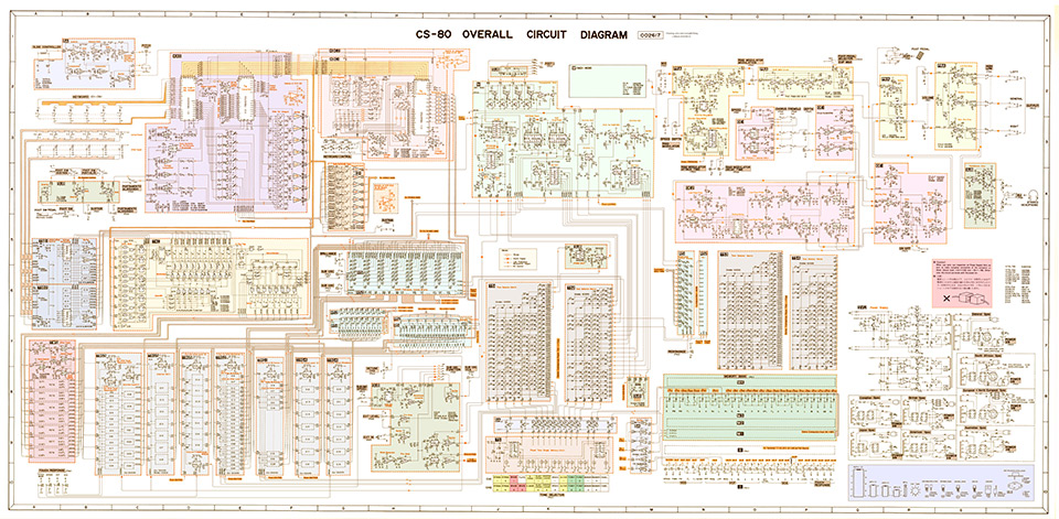
CS-80 Interactive Diagram
The following interactive diagram allows an easy navigation through the different blocks of the CS-80’s circuit diagram.
To get a short description of a block, hover the mouse over it. On mobile devices, do a long press instead.
To start browsing, click on a block or alternatively on one entry in the list below it. You’ll access a page dedicated to the block. In this page, the main diagram also contains hyperlinks, making it easy to follow the various signal paths.
Ribbon and Tuning (BA board)
This circuit is responsible for generating a voltage used as a reference pitch.
It corresponds to the tuning knobs and to the ribbon (or slide controller).This voltage is then fed into the KAS board.
Keyboard
Here are the sensors detecting the signals from the keyboard : note-on/note-off, velocity and aftertouch.
- Key press signals go to the KAS board.
- Velocity and aftertouch signals go to the TSB boards.
SUB (Portamento/Glissando & Sustain)
The settings of the portamento, glissando, and global sustain are defined here.This circuit is part of the SUB board.
KAS board (Key Assigner)
This board has two chips.
- The first one is responsible for assigning to each key pressed one of the 8 voices.
- The second one determines the voltage corresponding to a given key pressed.
KBC boards (Keyboard Control)
There are two identical boards. KBC1 is for the Brilliance Control and KBC2
is for Level Control. They allow the keyboard tracking of the cutoff frequency
and of the volume respectively.
SH board (Sample & Hold)
Two things happen here:
- The Sustain mode II is performed.
- The 8 key voltages are held with buffers.
TSB boards (Touch Sensor Boards)
Here arrive the 61 signals for velocity and aftertouch generated by the keys.
Both signals are merged before being multiplexed, and then passed to the TKC.
TKC board (Touch Key Controller)
The TKC receives the multiplexed velocity and aftertouch signals from the TSB
and routes them to the right voice in the TWS.The TKC follows the clock of the KAS. Therefore the 8 output signals are not produced continuously.
TWS board
The TWS has 8 identical circuits. Each one receives the combined velocity/aftertouch
signal and dispatches it to the TRGs as:
- Aftertouch
- Initial Touch (velocity)
- Initial Bend (velocity used for the pitch)
TRG boards
These five boards control the signals from the TWS before they are passed to
the mixing boards R51 & R52. They are used for:
- Init/After Level
- Init/After Brilliance
- Sub After VCO/VCF
- Init Pitch Bend
R51 & R52 (Resistor boards)
This is where the various control signals are mixed together before being
sent to the M boards.
SUB (Suboscillator)
This board holds many small circuits and appears in several places on this diagram.In this part are to be found:
- the Suboscillator (LFO)
- the noise generator
- the external input
SUB (Pulse Width Modulator)
Though only one is shown on the diagram, there are actually two identical circuits:
one for each synthesis line.This circuit is part of the SUB board.
T51 & T52 (Tone Matrix)
This is where the 11 presets for the first synthesis line are stored.
T53 & T54 (Tone Matrix)
This is where the 11 presets for the second synthesis line are stored.
R51 & R52 (Resonance)
The various resonance settings are mixed here before being sent to the M boards.These circuits are part of the R51 & R52 boards.
SUB (Sustain Comparator)
This small circuit determines the values of the sustain to be sent to the envelopes.This circuit is part of the SUB board.
Tone Selector
The tone selection circuitry is placed on two boards.There are 28 knobs; 14 for each synthesis line. The first 11 knobs select presets, the next 2 select a memory bank and the last one selects the front panel.
Memory Banks
There are 4 memory banks: M1 & M3 for the first synthesis line and M2 & M4 for the second.
Front Panel
Here are the knobs and sliders for the two synthesis lines.
SUB (Feet Selector)
There are two copies of this circuit. One for each synthesis line.This circuit is part of the SUB board.
M11 to M18 & M21 to M28
(Master boards)
These 16 boards form the two synthesis lines. Boards work in pairs associated
to a given played key by the KAS.(Master boards)
Each board is the base sound generator of the synthesizer and holds the following chips:
- 1 oscillator
- 1 waveshaper
- 2 state variable filters
- 1 envelope generator for the filters
- 1 envelope generator for the level
Channel Mixer
Here the output of the 16 M boards are mixed together to produce a mono signal.
Ring Modulator
This circuit applies the ring modulation to the output of the M boards.This circuit is part of the PRA board.
WAH Effect
This circuit applies the WAH effect to the output signal.This circuit is part of the PRA board.
EXP Effect
This circuit applies the EXP effect to the output signal.This circuit is part of the PRA board.
Mono/Stereo
This circuit receives the mono signal of the WAH effect circuit.
It then either reproduces this very signal to both its outputs, or produces a mix of
it with the Chorus/Tremolo signals.This circuit is part of the OE1 board.
Chorus Modulators (OE2 board)
This circuit holds two modulators used for the Chorus/Tremolo. A slow and a fast one.
Chorus/Tremolo
This circuit generates the Chorus/Tremolo effect thanks to a modulated delay.
The delay (a Bit Bucket Device) produces two outputs which pass through modulated mixers
to create the effect.This circuit is part of the OE1 board.
Pre-amplifier
This circuit sets the levels of the Left, Right and General (Mono) outputs.This circuit is part of the PRA board.
SUB (Headphone Amplifier)
This circuit adjusts the levels of the Left and Right outputs of the Pre-Amp for a headphone.This circuit is part of the SUB board.
Power Supply (SVU)
The common and country specific power supply circuitry.
You can access the pages dedicated to the different boards either from the diagram above, or from the list below:
- Ribbon and Tuning (BA board)
- Portamento/Glissando & Sustain
- KAS board (Key assigner)
- SH board (Sample & Hold)
- KBC boards (Keyboard Control)
- Keyboard
- TSB boards (Touch Sensor)
- TKC board (Touch Key Controller)
- TWS board
- TRG boards
- R51 & R52 (Resistor boards)
- Resonance Mixing
- Tone Selector
- Front Panel
- Memory Banks
- T51, T52, T53 & T54 (Tone Matrix)
- Sustain Comparator
- Suboscillator
- Pulse Width Modulator
- Feet Selector
- M boards (Master)
- Channel Mixer
- Ring Modulator
- WAH Effect
- EXP Effect
- Chorus/Tremolo
- Pre-amplifier
- Headphone amplifier
- Power Supply (SVU)
